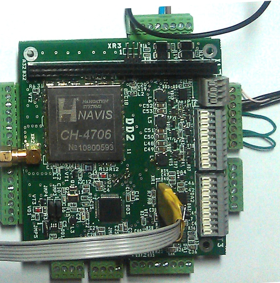
Tweet So how to arrange data exchange through Modbus RTU? Answering multiple requests and inspired by @burgua, @maxmaxmax and other people I have finally decided to write down a second part of the manual 🙂 In order to start up data exchange protocol, it is required to implement it both on master (in our case PC) and slave (board RS-485 with port). All this will work with RS-485 – USB adapter. Let’s have a look at Modbus RTU configuration implementation, where PC is a master (i.e. query sender) and a board is a slave (query responding unit). For the very beginning, one should define address chart to be completely matching address map set in the controller which we are going to use: Click to toggle codeblock 1 2 3 4 5 6 7 8 9 10 11 12 13 14 15 16 17 18 19 20 21 22 23 24 25 26 27 namespace Modbus { public enum ModbusMap { ADR_STAT = 0, ADR_ADC_STATUS = 1, ADR_ADC_RESULT = 2, ADR_ADC_ENG_VALUES = 12, ADR_TIME = 22, ADR_BINR_STATE = 25, ADR_BINR_ATTEMPTNUM = 26, ADR_STATUS_IOBSM = 27, ADR_DIVISOR_COUNTER = 28, ADR_TIME_SCALE = 29, ADR_GSK_RES = 55, ADR_OSK_RES = 83, ADR_CMD = 111, ADR_NAV_TASK_STATE = 112, ADR_NAV_TASK_CORRECT_ORB_INDEX = 113, ADR_NAV_TASK_CORRECT_ORB_INDEX_ITER = 114, ADR_COUNT_GPS_DATA = 115, ADR_COUNT_GPS_TASK = 116, ADR_FIRST_INDEX_GPS_TASK = 117, ADR_IS_CYCLE_READ_MODE = 118, ADR_STORE_DIVISOR = 119 } } namespace Modbus { public enum ModbusMap { ADR_STAT = 0, ADR_ADC_STATUS = 1, ADR_ADC_RESULT = 2, ADR_ADC_ENG_VALUES = 12, ADR_TIME = 22, ADR_BINR_STATE = 25, ADR_BINR_ATTEMPTNUM = 26, ADR_STATUS_IOBSM = 27, ADR_DIVISOR_COUNTER = 28, ADR_TIME_SCALE = 29, ADR_GSK_RES = 55, ADR_OSK_RES = 83, ADR_CMD = 111, ADR_NAV_TASK_STATE = 112, ADR_NAV_TASK_CORRECT_ORB_INDEX = 113, ADR_NAV_TASK_CORRECT_ORB_INDEX_ITER = 114, ADR_COUNT_GPS_DATA...
Read More


